BLE Satellite
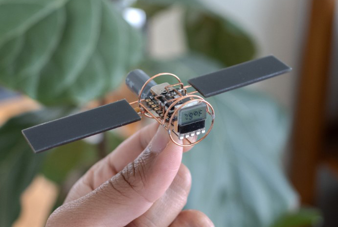
I have previously built solar-powered, temperature monitoring satellites with ATTiny microcontrollers, but I’ve been wanting to build one with a radio on it. So, when I came across the XIAO nRF52840 devboard from Seeed Studio, I knew I had found the perfect candidate. It even has a built-in LDO and battery charger! This board is built around Nordic Semi’s nRF52840 SoC, which I’m very familiar with since all of Particle’s Gen3 hardware uses it.
Parts List
- Seeed Studio’s XIAO nRF52840 dev board. You don't need the more pricey "BLE Sense" version for this build.
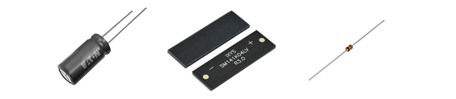
- Eaton 50F, 3.8V hybrid supercapacitor
- SM141K04LV solar cells x 2
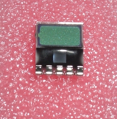
- LCD module
- 20 AWG copper wire
- SHT31 sensor breakout board
- 1N4148 diode or any small rectifying diode
Tools
- Soldering Iron. Any good soldering iron above 60W will work. I recently started using Pinecil, and have been enjoying using it a lot. The Hakko FX888D is a solid choice as well, or a Weller.
- Solder. I have not had good luck with lead-free solder.
- Flux. I use this flux pen which is very convenient to dispense.
- Flat needle nose pliers. These flat ones are awesome, while these thin ones are good for tighter bends.
- Flush cutter. I like this one from Xuron.
- Steel wool to clean the joints.
- Printer for printing templates.
(*some of the product links include Amazon affiliate links)
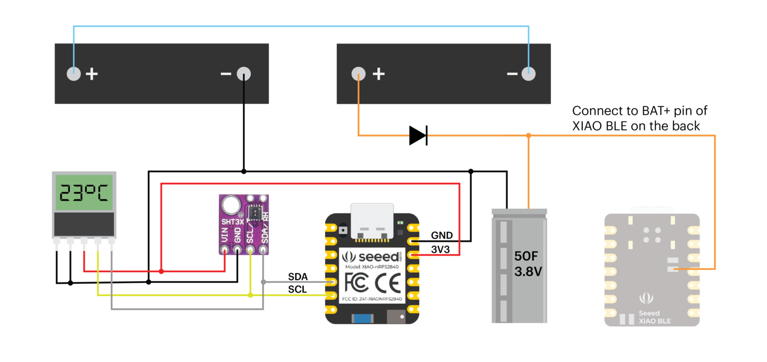
Schematic
Display
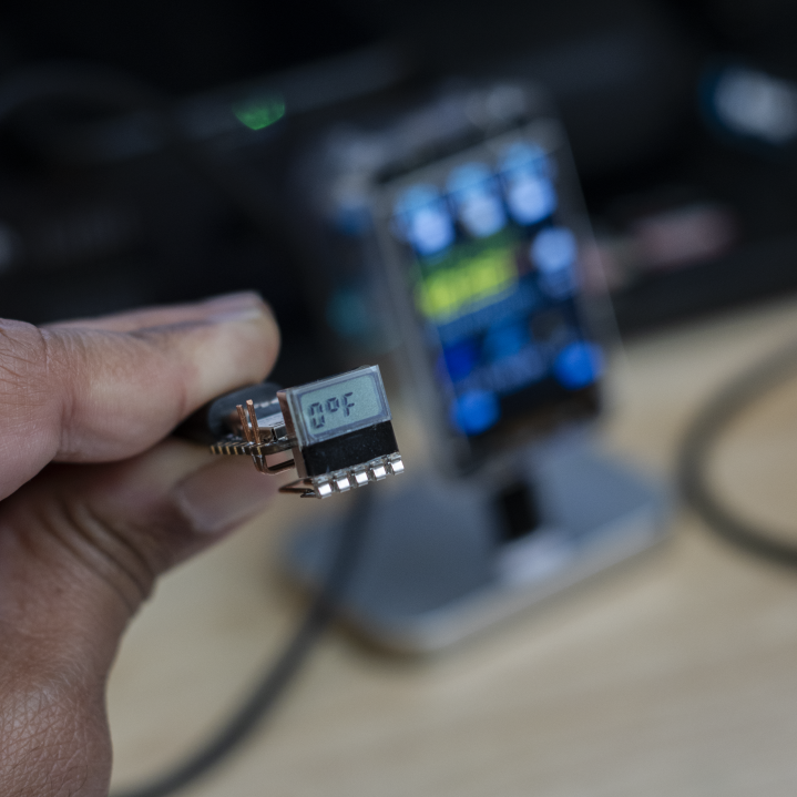
I found this little LCD module while looking for small LCD screens with built-in controllers. These are surprisingly hard to find! The ones you can find are usually too big, and the small ones don’t have a built-in controller. So, this one is a unique find! It has an onboard PCF8576C LCD controller that communicates over I2C. You can find more about it here.
The LCD and the sensor are both connected to the XIAO nRF52840’s I2C pins and are powered by the 3.3V pin. Ensure that the sensor board has pull-up resistors on the SDA/SCL pins, and if not, then you’ll need to add them externally. 4.7K works well.
Sensor
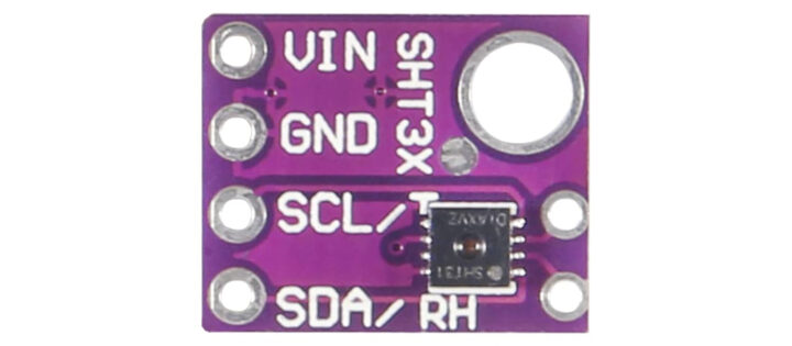
I made a small breakout board for the SHT31 temperature and humidity sensor. You can use other off-the-shelf breakout boards for this sensor as shown above or use a completely different sensor, like say, the BME280.
Power
The XIAO has a built-in battery charger (BQ25101) whose pads are exposed on the bottom of the board. I simply connected the supercapacitor to these pins. The solar cells are connected in series and charge the capacitor directly via a reverse polarity protection diode. I have used 1N4148, but you can use any small signal diode here. If these solar cells are not available, you may substitute them with others that are in the same voltage range. You can connect them in series or parallel to get to a total voltage that is close to the maximum voltage of the supercapacitor.
If you dig deeper, you’ll notice that each solar cell produces about a 2.23V peak. So two of them in series would lead to 4.46V, which is a bit high for the supercapacitor. This is where we rely on the forward voltage drop of the diode in series, which is about 0.6V. The supercapacitor thus, only sees about 3.86V across it. In my observation, it has never reached this high. This obviously is not the most efficient way to charge the supercap. The diode drop will change with current and temperature. One would ideally use an energy harvester or an MPPT controller to charge the supercap, but for our intention and purposes, the diode would do just fine. In future revisions, I plan to use an energy-harvesting breakout board to make the overall system more efficient and safe. Possibly using the AEM10941 solar harvester from E-peas or the SPV1050 from ST Micro. Let me know if you get to it before I do!
Note that even though the supercapacitor is connected to the battery pin of the XIAO, you should not use it to charge the capacitor since the voltage would be too high. The battery charger is set to charge at 4.2V but the max voltage for the supercapacitor is 3.8V. Subjecting it to a higher voltage will damage it.
You ought to be careful with the supercapacitor, as it can dump upwards of 9 Amps if shorted. This means you can get a nasty burn, or in the worst case, it could lead to a thermal runaway. The voltage however is safe to touch and work with, and it won’t zap you 🔥
Firmware
The firmware is a modified version of the BLE beacon example from Adafruit. We essentially populate the BLE beacon packet with temperature and humidity readings. This way the satellite never needs to "pair" with a host device, and simply transmits a beacon that is available to any device that is listening. The device consumes an average current of 100uA. I think there is room for further optimization, but I have not looked into it much.
Complete source code for this project can be found on the project's GitHub page.
Learn how to set up the Arduino IDE to work with the XIAO on Seeed Studio’s website here.
/*********************************************************************
 Project: BLE Satellite
 Author: Mohit Bhoite
 Date: 01 December 2023

 Uses BLE library and code example by Adafruit.

 Adafruit invests time and resources providing this open source code,
 please support Adafruit and open-source hardware by purchasing
 products from Adafruit!

 MIT license, check LICENSE for more information
 All text above, and the splash screen below must be included in
 any redistribution
*********************************************************************/
#include <bluefruit.h>
#include <Wire.h>
#include <cdm4101.h>
#include "Adafruit_SHT31.h"
#include <Adafruit_FlashTransport.h>

Adafruit_FlashTransport_QSPI flashTransport;

// Beacon uses the Manufacturer Specific Data field in the advertising
// packet, which means you must provide a valid Manufacturer ID. Update
// the field below to an appropriate value. For a list of valid IDs see:
// https://www.bluetooth.com/specifications/assigned-numbers/company-identifiers
// 0x004C is Apple
// 0x0822 is Adafruit
// 0x0059 is Nordic
#define MANUFACTURER_ID   0x004C

// Setup a dummy BLE UUID
uint8_t beaconUuid[16] =
{
  0x01, 0x12, 0x23, 0x34, 0x45, 0x56, 0x67, 0x78,
  0x89, 0x9a, 0xab, 0xbc, 0xcd, 0xde, 0xef, 0xf0
};

// A valid Beacon packet consists of the following information:
// UUID, Major, Minor, RSSI @ 1M
// We are setting up a dummy packet which we will update it with temp and humi values in loop()
BLEBeacon beacon(beaconUuid, 0x0102, 0x0304, -54);

char data[25];
CDM4101 LCD;
Adafruit_SHT31 sht31 = Adafruit_SHT31();

void setup()
{
  Wire.begin();
  LCD.Init();
  sht31.begin(0x44);

  LCD.DispStr("Test");
  delay(2000);
  //Serial.begin(115200);

  // Uncomment to blocking wait for Serial connection
  // while ( !Serial ) delay(10);

  //Serial.println("Bluefruit52 Beacon Example");
  //Serial.println("--------------------------\n");

  Bluefruit.begin();
  flashTransport.begin();
  flashTransport.runCommand(0xB9);
  flashTransport.end();

  Bluefruit.autoConnLed(false);
  // Setting the TX power to lowest possible value to lower total power comsumption
  // A low value like this significantly shortens the range of the radio
  // Find a value that works best for you
  // Check bluefruit.h for supported values
  Bluefruit.setTxPower(-40);

  // Manufacturer ID is required for Manufacturer Specific Data
  beacon.setManufacturer(MANUFACTURER_ID);
  //Following is dummy data. We will update it with temp and humi values in loop()
  beacon.setMajorMinor(71, 61);

  // Setup the advertising packet
  startAdv();
}

void startAdv(void)
{
  // Advertising packet
  // Set the beacon payload using the BLEBeacon class populated
  // earlier in this example
  Bluefruit.Advertising.setBeacon(beacon);

  // Secondary Scan Response packet (optional)
  // Since there is no room for 'Name' in Advertising packet
  Bluefruit.ScanResponse.addName();

  /* Start Advertising
   * - Enable auto advertising if disconnected
   * - Timeout for fast mode is 30 seconds
   * - Start(timeout) with timeout = 0 will advertise forever (until connected)
   *
   * Apple Beacon specs
   * - Type: Non connectable, undirected
   * - Fixed interval: 100 ms -> fast = slow = 100 ms
   */
  //Bluefruit.Advertising.setType(BLE_GAP_ADV_TYPE_ADV_NONCONN_IND);
  Bluefruit.Advertising.restartOnDisconnect(true);
  Bluefruit.Advertising.setInterval(3200, 3200);    // in unit of 0.625 ms
  Bluefruit.Advertising.setFastTimeout(30);      // number of seconds in fast mode
  Bluefruit.Advertising.start(0);                // 0 = Don't stop advertising after n seconds
}

void loop()
{
  //read temperature and humidity from the SHT31 sensor
  int temperature = (sht31.readTemperature()*1.8)+32;
  int humidity = sht31.readHumidity();

  //ensure the readings are valid before displaying them
  if (! isnan(temperature))
    {
      sprintf(data,"%doF",temperature);
      LCD.DispStr(data);
    }
  delay(2000);
  if (! isnan(humidity))
    {
      sprintf(data,"%drH",humidity);
      LCD.DispStr(data);
    }
  delay(2000);
  //load the BLE packet with latest temp and humi values
  beacon.setMajorMinor(temperature,humidity);
  Bluefruit.Advertising.setBeacon(beacon);

}
Construction
As always, I begin the construction by breadboarding the entire circuit first. Once I have everything working properly, and have optimized for power, I move on to the next step of actual construction.
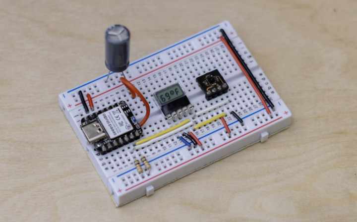
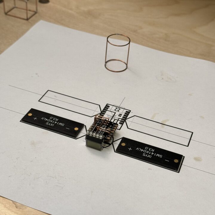
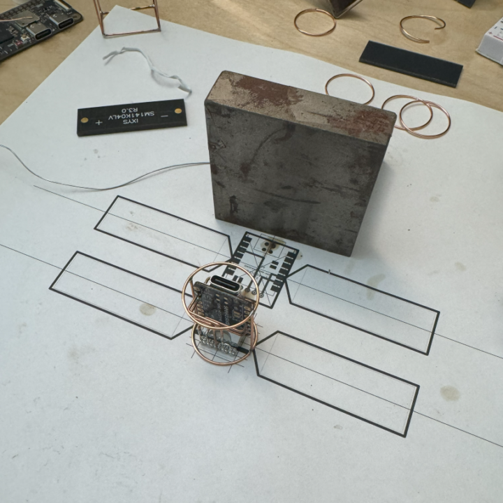
The frame is made out of 20 AWG copper wire, but you can use brass as well. I made a quick video on how you can turn a brass or copper wire into a straight rod. I designed a true-to-scale template using Autodesk Eagle to help guide the construction. I use a pair of flat-nose needle pliers to bend the rods and a diagonal cutter to cut them to length. The frame is connected to the GND net, so routing becomes much easier. I used a template printed on paper to guide the overall construction. You can download the PDF version of the template here.
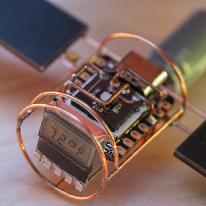
This was the first time I tried using circular bends in my construction. It turned out to be a lot easier than I thought (no pun intended). I wrapped the copper wire around an 18650 battery a few times and then cut it into several rings. (Ensure that the rings are flat before you solder their ends together.) I lined up the ring against a flat square and soldered in the ribs. I repeated that on the other side to form a little tube-like structure. This becomes the main body of the satellite.
If you experience difficulty in getting the solder to stick to the copper, try polishing it with steel wool beforehand, to remove any surface oxidation. Apply a generous amount of flux to the joint to help the solder wet properly. I set my soldering iron to around 750F. Copper is a really good conductor of heat, so you have to be quick on the solder joint, or else the adjacent joints will start to melt.
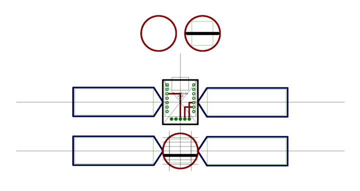
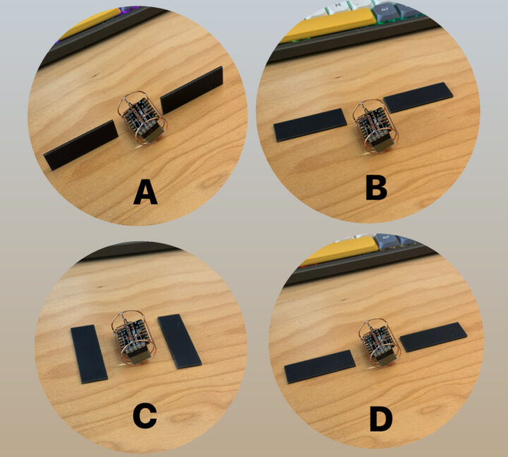
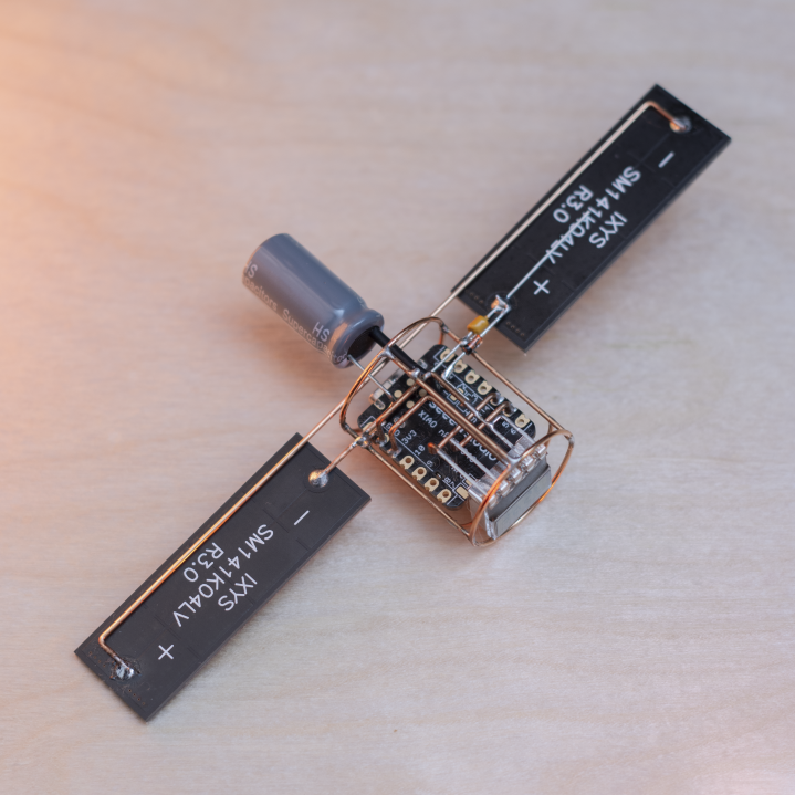
I played with a few arrangements for the solar cells and eventually landed on option B. I decided not you add additional frames around the solar cells for a cleaner look. You could try one of the other options, or something entirely different!
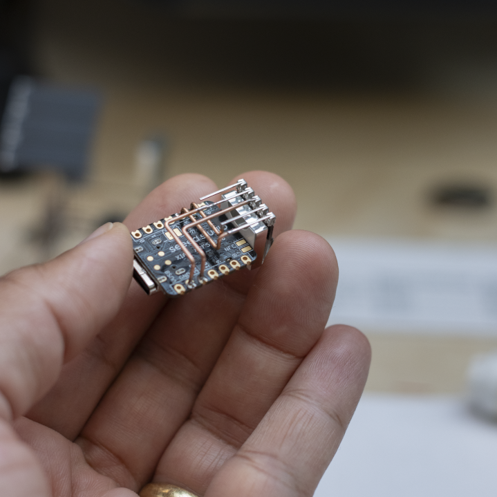
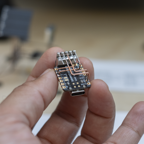
A quick sanity check before I moved forward with soldering in the solar cells and the supercapacitor.

I added a heat shrink tube around the positive terminal for the supercapacitor to avoid the chance of accidental shorting as I soldered it in place. I also added a 0.1uF bypass capacitor (yellow component in the photo) between the positive terminal of the solar panel and GND for additional structural support.
If you found this documentation useful, please consider supporting me on Patreon or buying me coffee! Thank you!