Boron Lander
Last updated: 23 Sept, 2023, San Francisco
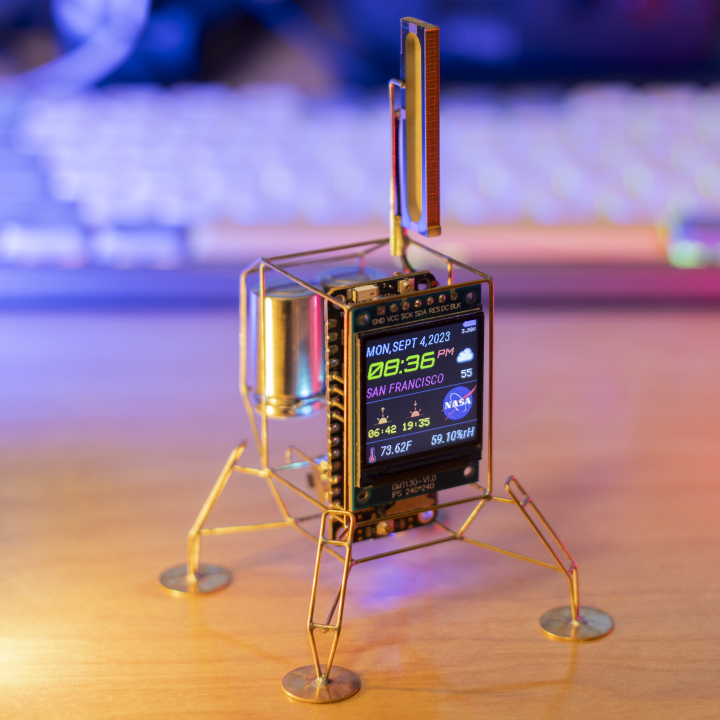
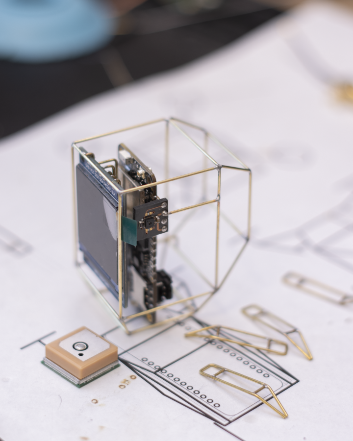
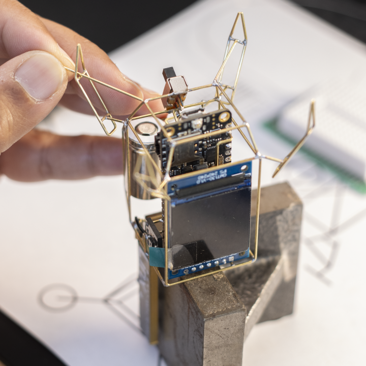
The Boron Lander is the latest in the series of planetary lander-inspired circuit sculptures. This is my first attempt at building one with cellular connectivity, which is provided by the Particle Boron, hence the name. I previously built a similar version using the Particle Photon 2, which provides connectivity over Wi-Fi instead of cellular.
As I have built these free-formed circuit sculptures over the years, I have come to realize that the lander or space-inspired form factor works well with this technique. The brass or copper interconnects are used for electrical connections as well as structural elements. You could 3D print the structure and stick a circuit board inside it—but where is the fun in that?
Please note that this is not a step-by-step tutorial, but rather a documentation of how I built the lander. There are countless ways to approach a build like this depending on skill set, available tools, and desired aesthetics. Use this as a reference, not a blueprint.
Parts List
- Particle Boron 404X or your preferred MCU board
- 1.3” 240x240 IPS TFT ST7789 display
- SHT31 sensor breakout board
- 14250 Li-Ion battery
- Linx ANT-LTE-SP610-T antenna
- uFL pigtail
- 20 AWG brass or copper rods
- 14mm brass discs for landing pads
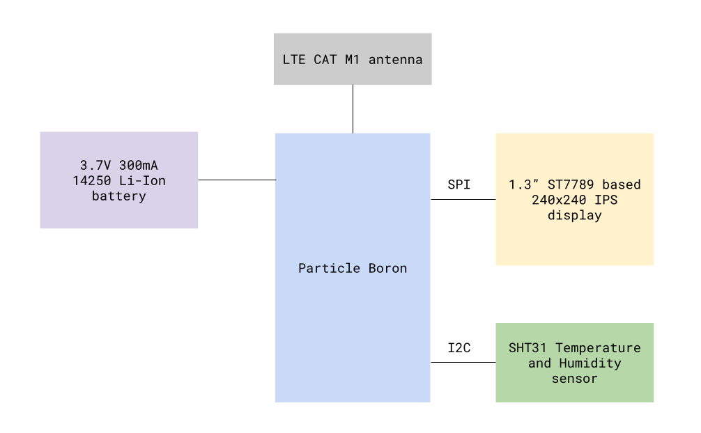
Block Diagram
There are four main components in this design: the MCU board, display, sensor, and battery. The display operates at 3.3V and connects over SPI, while the sensor communicates over I2C. Power is provided either by battery or USB. For Particle Boron, a cellular antenna is required.
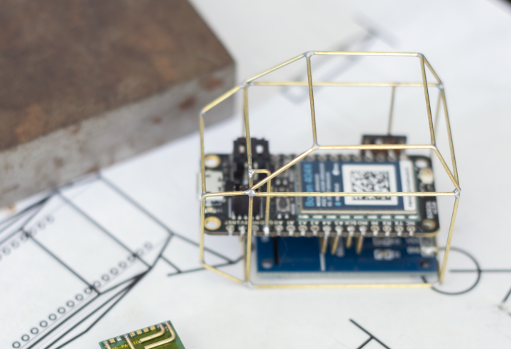
Controller
At the heart of this sculpture is the Particle Boron 404X, a cellular IoT devkit in Feather form factor. It comes preinstalled with Particle Device OS and provides LTE CAT M1 cellular connectivity. Data is free for your first 100 devices in North America.
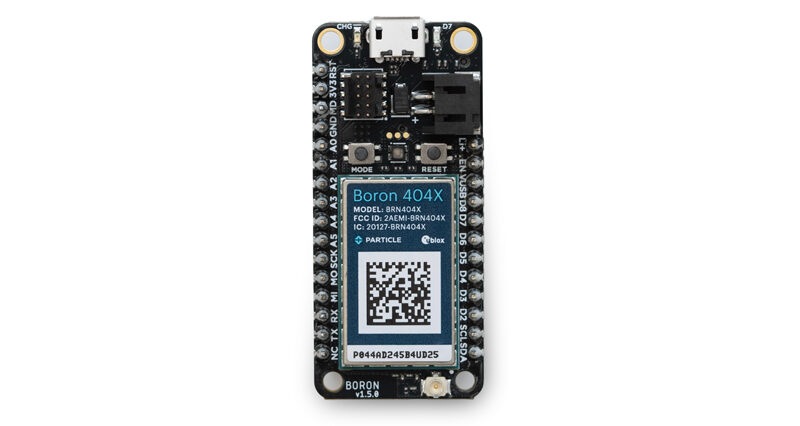
Developing on the Boron is similar to Arduino, ESP32, or RP2040-based boards, but you’ll need Particle Workbench instead of the Arduino IDE.
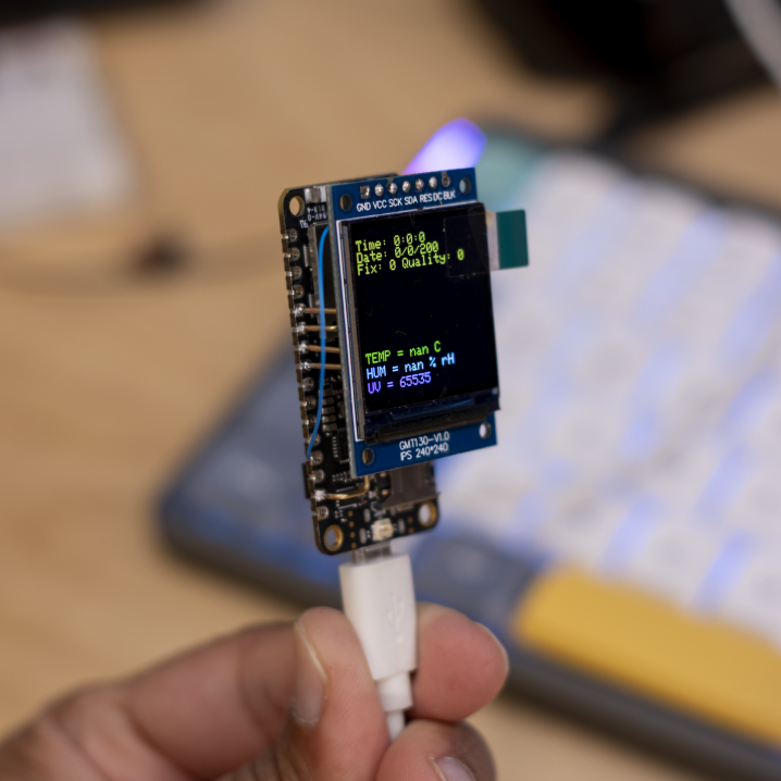
Display
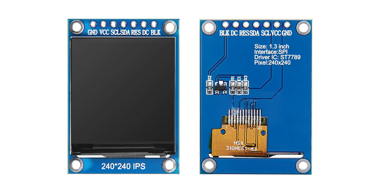
The 1.3” 240x240 16-bit color IPS TFT display (ST7789 controller) offers sharp visuals, works at 3.3V, and communicates via SPI. I’m using Adafruit’s ST7735 library, but Bodmer’s TFT_eSPI is also excellent.
Sensor
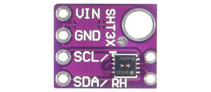
I made a custom breakout board for the SHT31 temperature and humidity sensor, but off-the-shelf boards work just as well.
Power
Use these batteries with extreme caution. Improper use can result in fire.
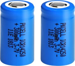
The sculpture runs on a 3.7V 300mAh 14250 Li-Ion battery. The Boron has an onboard charger and fuel gauge. Do not parallel-connect Li-Ion cells unless properly matched.
If you prefer, use USB power or a protected LiPo like this one.
Antenna
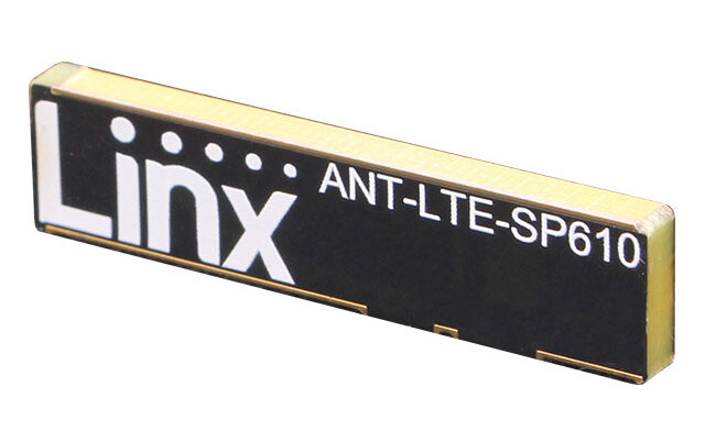
I used a Linx PCB monopole antenna for its smaller size and aesthetics. It’s connected via a uFL pigtail.
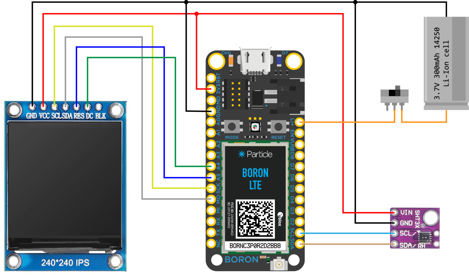
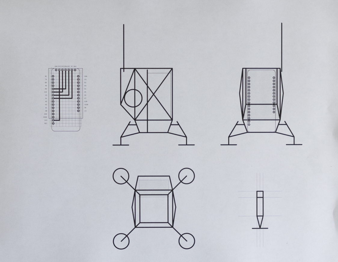
Schematic Diagram
### Pin Connections
Display
- GND → Boron GND
- VCC → Boron 3V3
- SCL → Boron SCK
- SDA → Boron MOSI
- RES → Boron A5
- DC → Boron A4
- BLK → Leave unconnected

Sensor
- VIN → Boron 3V3
- GND → Boron GND
- SCL → Boron SCL
- SDA → Boron SDA

Battery
+ → Boron Li+ (via switch)
– → Boron GND
Construction
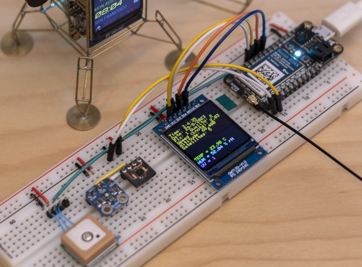
I always start by prototyping on a breadboard to finalize components and connections.
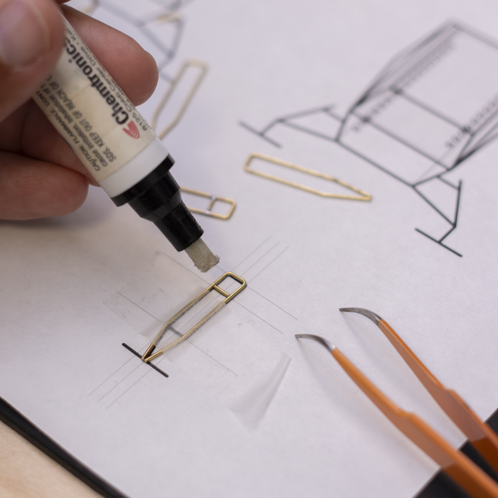
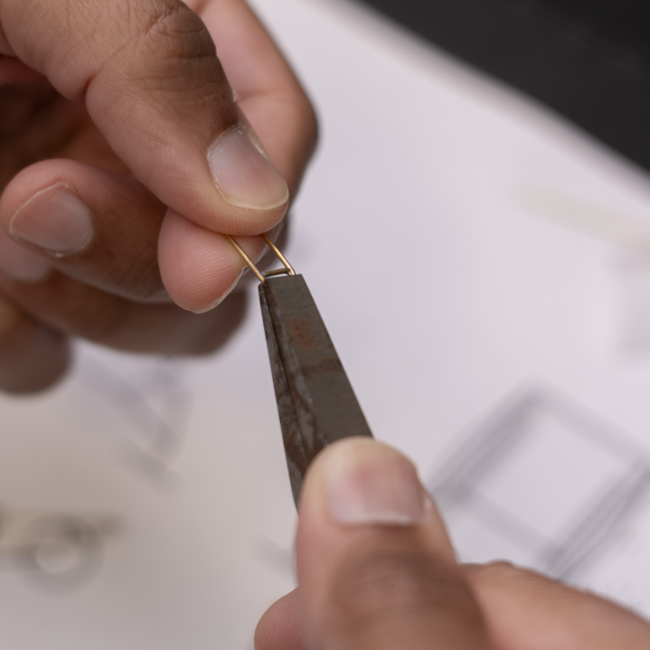
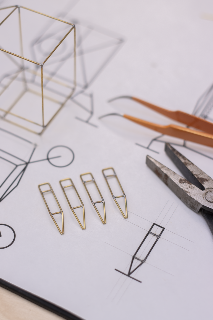
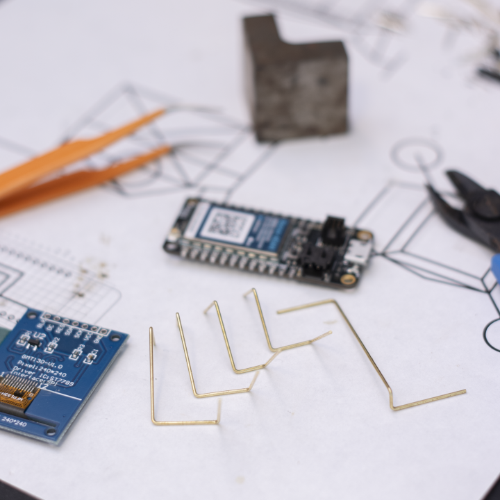
The frame is made from 20 AWG brass rods.
After cutting and bending, I fix the rods onto the template using masking tape for soldering. Flux is applied on each joint, and I clean connections with fine steel wool.
I used scrap PCBs as soldering jigs to keep parts aligned.

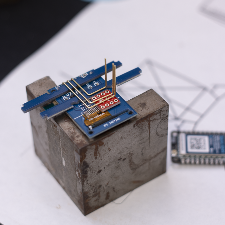
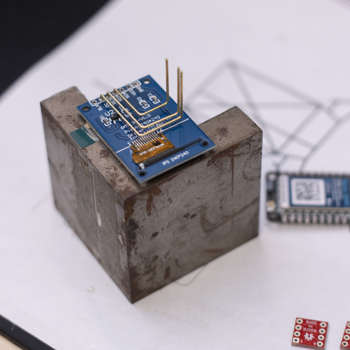
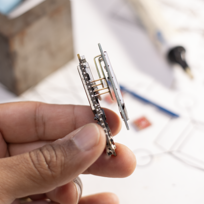
Always a good idea to test the subsystems as you go!
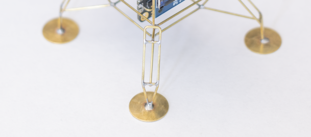
The landing pads are 14mm brass discs from Etsy. You can also make your own by punching discs. Solder them last to avoid alignment issues.
Firmware
A lot of the heavy lifting is done by Adafruit's device libraries. They put out a ton of really amazing open-source device libraries and hardware. Please consider supporting them by purchasing their products! I’m using the Adafruit ST7735 and GFX libraries for the display, and the SHT31 library for the sensor.
The complete source code for this project can be found on my GitHub.
In addition to downloading the firmware onto your device, you'll also need to set up the Particle Webhook integrations on the Particle console to fetch the weather forecast and sunrise/sunset time data.
Setting up Particle Webhooks
You can find the complete documentation on Particle Webhooks here.
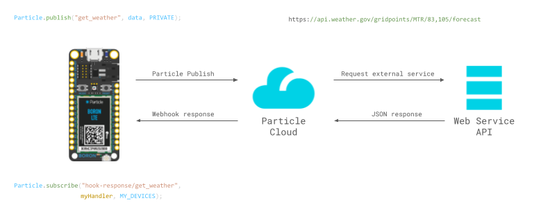
Essentially, Particle Webhook allows you to connect your Particle device to different services on the internet. In this project, we are relying on the Webhooks to fetch and parse the weather forecast and sunrise/sunset times and send it back to our device. Every time we do a Particle.publish, we trigger the associated Webhook, which in turn returns us a nicely parsed data string. We fetch this data by subscribing to the associated webhook response. All of this magic happens asynchronously in the backgr...
If all of this sounds confusing or overwhelming to you, don't worry! You can follow some of the documentation on Particle's website or join the online community to find answers.
Setting up webhook to fetch sunrise and sunset times
We will be using the ipgeolocation.io Astronomy API to fetch the sunrise and sunset times. You'll first need to get an API key from them. Create a free account and follow the instructions on their website to get an API key here.
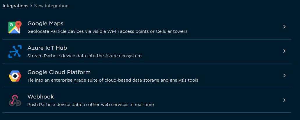
Now go to Integrations in your Particle Console. Click on +ADD NEW INTEGRATION.
Set up the webhook as follows. Under the URL block, paste the link with your API key and location:
https://api.ipgeolocation.io/astronomy?apiKey=123456789&lat=37.89&long=-122.48
To check if your API is working, you can paste the above link (replace 123456789 with your API key and plug in the desired latitude and longitude) into your browser. You should get a JSON response similar to this:
{
  "location": {
    "latitude": 37.89,
    "longitude": -122.48
  },
  "date": "2023-09-04",
  "current_time": "18:28:22.248",
  "sunrise": "06:58",
  "sunset": "19:25",
  "sun_status": "-",
  "solar_noon": "13:02",
  "day_length": "12:07",
  "sun_altitude": 8.83,
  "sun_distance": 150150216.08,
  "sun_azimuth": 262.66,
  "moonrise": "15:46",
  "moonset": "-:-",
  "moon_status": "-",
  "moon_altitude": 18.97,
  "moon_distance": 371243.28,
  "moon_azimuth": 152.35,
  "moon_parallactic_angle": -24.38
}
Go to Advanced settings and select Custom under the query parameters.
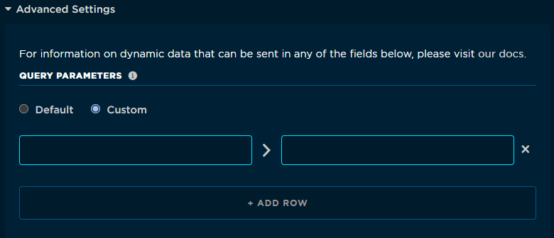
To extract just the sunrise and sunset times, we will create a parser under the Response Template, which can be found under the advanced settings. This way, only the sunrise and sunset times are sent to your device instead of the entire JSON response. If you are interested in fetching and displaying other parameters like the moonrise times, modify the response template accordingly.
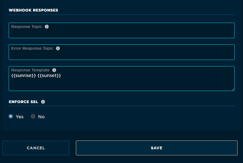
Hit Save and your webhook should now be set up.
Setting up weather forecast webhook
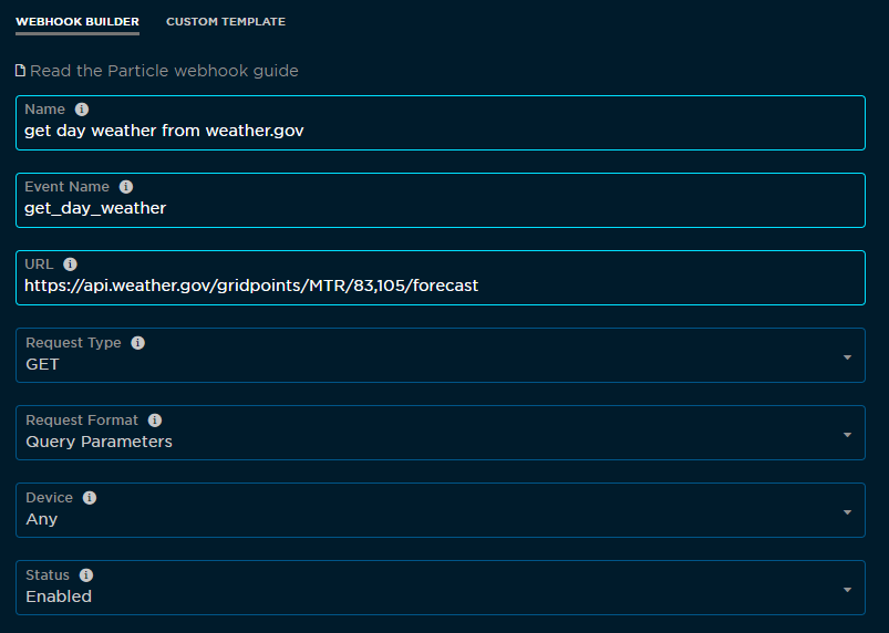
Go to Integrations in your Particle Console. Click on +ADD NEW INTEGRATION.
We will be using the weather.gov's free API service to fetch the weather forecast data. You will have to adjust the URL with grid points for your location. It is currently set to fetch weather for San Francisco.
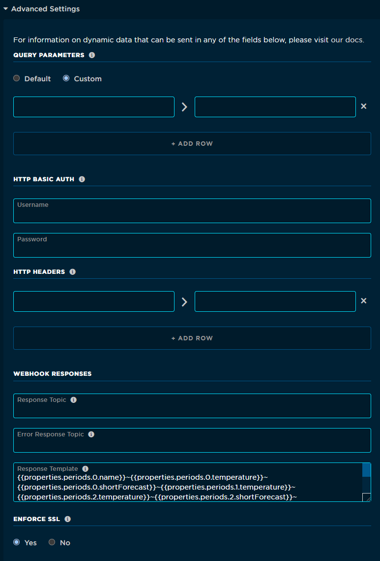
Create a webhook template to parse the relevant information:
{{properties.periods.0.name}}~{{properties.periods.0.temperature}}~{{properties.periods.0.shortForecast}}~{{properties.periods.1.temperature}}~{{properties.periods.2.temperature}}~{{properties.periods.2.shortForecast}}~{{properties.periods.3.temperature}}~{{properties.periods.4.temperature}}~{{properties.periods.4.shortForecast}}~{{properties.periods.5.temperature}}~{{properties.periods.6.temperature}}~{{properties.periods.6.shortForecast}}~{{properties.periods.7.temperature}}~
Hit Save and your weather Webhook should now be all set.
Thoughts on building your own lander
If you are new to the world of microcontrollers, electronics, or embedded systems, this project might not be the best place to start. I’d recommend getting yourself a Particle Photon 2 or some other MCU dev board like the ESP32 C3 Wroom or Raspberry Pi Pico. Learn by building simple breadboarded projects with displays and sensors. Next, learn to solder together simple brass frames and shapes. After you feel comfortable with putting together simple projects, gradually move on to combining free-form solder...
I'm actively updating this documentation. So check back for more details. If you have questions in the meantime, send me an email or comment on the project's GitHub page.
If you found this documentation useful, please consider supporting me on Patreon or Ko-fi. Thank you!