Dizzy
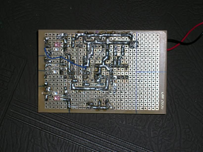
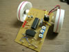
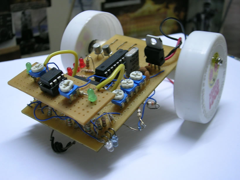
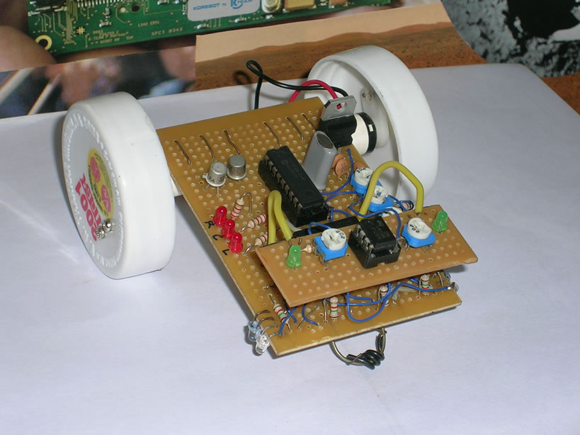
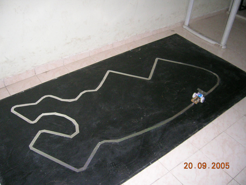
Dizzy is my first successful line following robot built back in 2005. It has an average speed of 30cm/sec, enough to get him the first prize at a local robotics competition. Usually line following robots are considered simple to build but what I learned from this project is that, making the robot follow a line is the easy part, but making it go fast at the same time is something different.

Since Dizzy was my first line follower, I decided to keep the design as simple as possible and started with a three sensor configuration. When it was tested on a straight line with few smooth turns here and there, the results were very satisfying. Then came the bad news, Dizzy had a very hard time dealing with sharp turns and 90 degree junctions. At higher speeds, the sensors started overshooting the line to such an extent that the recovery became impossible. The only solution to this problem was to reduce the speed of the motors. But this turns out to be a huge compromise since this robot was suppose to enter a line following ‘racing’ competition. I concluded that the sensor placement was the root cause of this problem. Since the sensors were placed too close to each other, the robot had a hard time detecting the sharp turns at higher speeds.
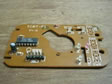
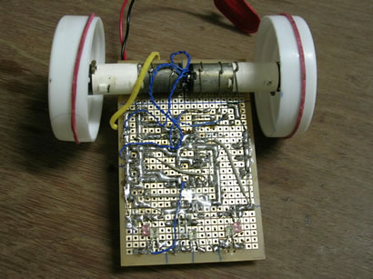
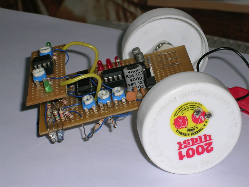
At this stage, time was running out, I had only one night left before the competition and very few options were available. Changing the sensor placement was not an option due to the lack of space available on the already congested PCB. So, I finally decided to add an extra pair of sensors. This increased the resolution and I had more accurate data from the sensors to work with.
Sensors:
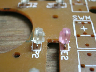
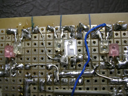
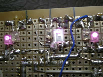
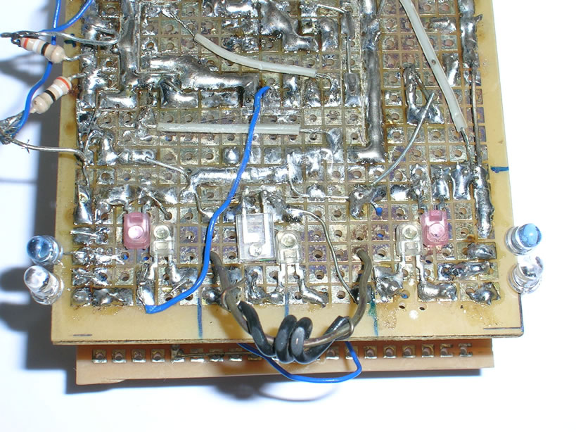
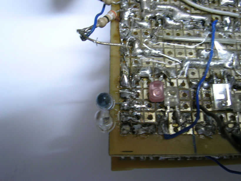
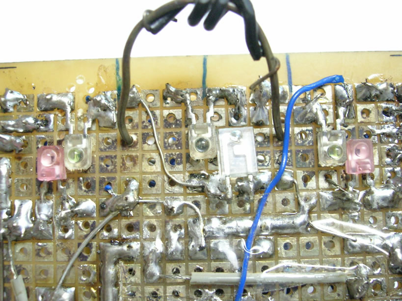
 The sensors used were IR emitter and receiver pair hacked from an old computer mouse. These are an excellent choice for such applications. The best thing about these sensors is that they have a very narrow beam width, so they can be placed very close to each other without worrying about the interference. Secondly, they are dirt cheap. You can buy an old mouse for about Rs.10 to Rs.15. Look for the really old ones since they have 4 pairs of IR sensors while the new ones have just 2. Old is gold after all!
Be careful while soldering or desoldering these sensors. Since they have very small terminals left, overheating may render them useless ( I learned it the hard way) . And remember to keep the supply voltage to these sensors below 2volts, otherwise they will overheat and get damaged (again learned it the hard way)
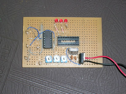
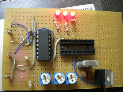
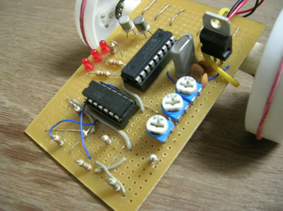
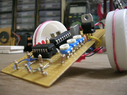
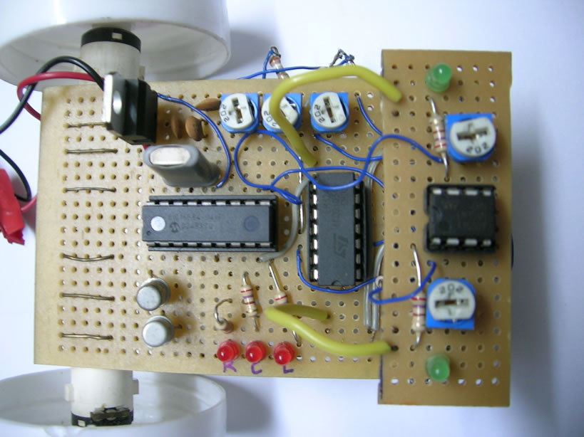
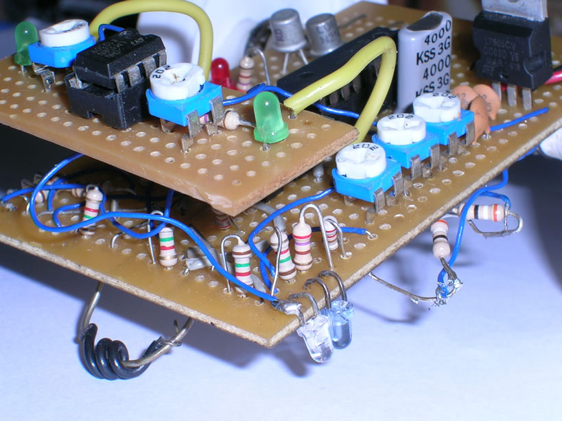
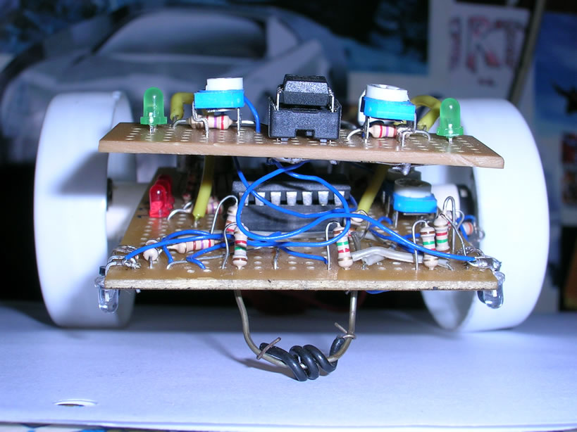
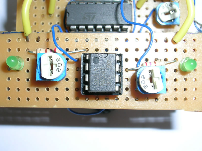
I used an LM324 general purpose quad OpAmp IC to filter the information coming from the sensors so that the output would go high ‘only’ when a white surface was detected. The threshold voltage was varied using a 2k pot. Later when the two extra sensors were added, I made use of LM358 dual opamp. It was soldered on to a new pcb and attached to the main board using a pair of stiff wires.

Motors:
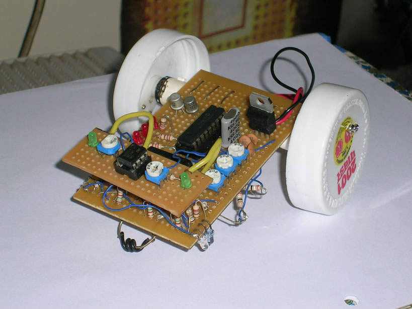
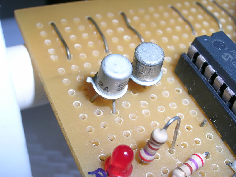
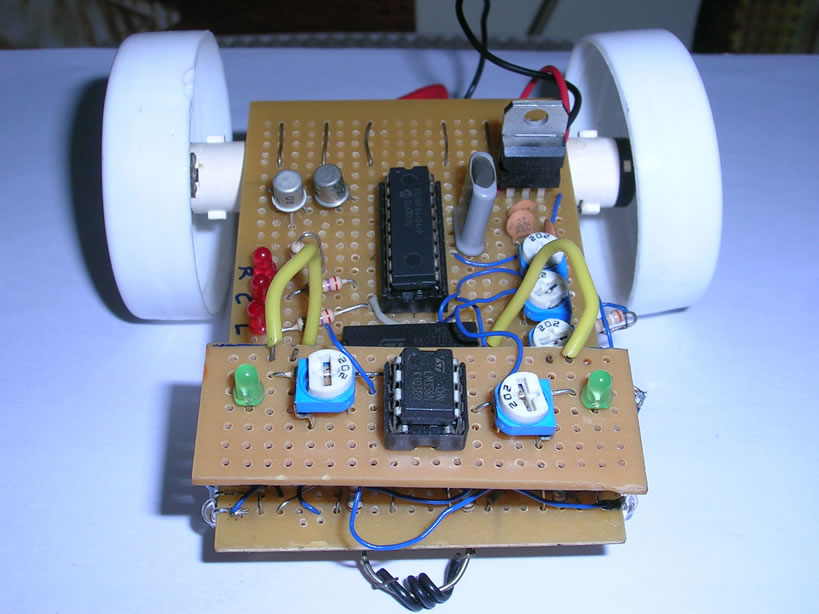
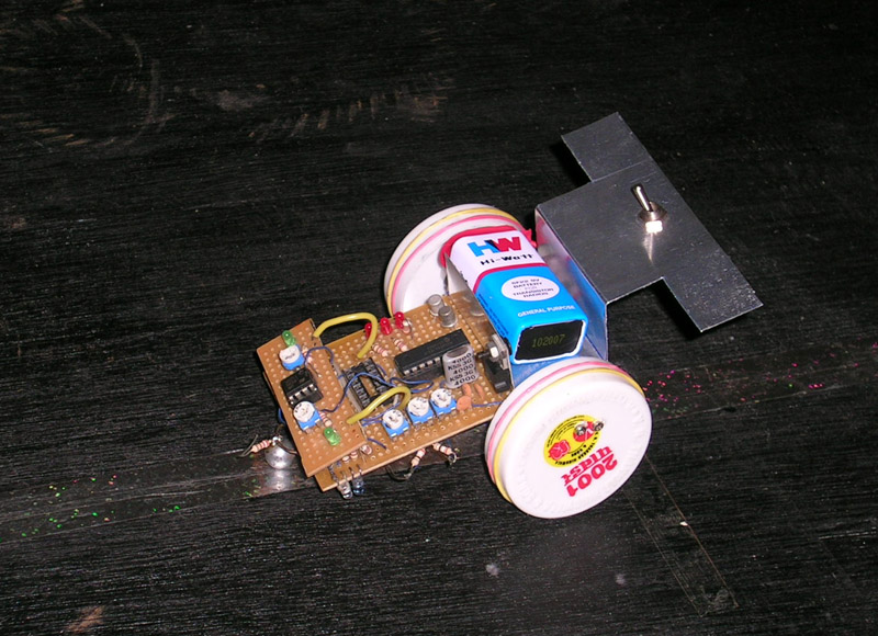
Dizzy uses two miniature geared motors having operating voltage of about 3volts. They can even be driven by a single 2n2222 transistor! Their rpm is somewhere around 60 and possess enough torque for small applications. I bought them from Servo Electronics at Lamington Road, Grant road east, Mumbai for Rs.200 each. These are my personal favorites.
The motors were turned on/off using 2N2222A NPN transistors, one for each motor. Since the direction of the motors was going to remain the same, the use of H-bridge was unnecessary.
Microcontroller:
Dizzy uses PIC16F84A microcontroller for processing all the sensor data and to produce the appropriate control signals for the motors. This microcontroller is very easy to work with. The software for dizzy was written in assembly using the MPLAB software available freely at www.microchip.com
While all of the 5 sensor pairs could have been used, I decided to go with only 2 of them. Only the extreme right and left (the new additions) were utilized. This last minute switch made all the difference during the competition. It made dizzy work reliably and run much faster than her competitors. Dizzy followed a zig-zag motion while following the line, hence the name ‘Dizzy’.
Now the new software code utilizes all of the 5 sensors.
Complete schematic can be found here.