Kida
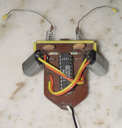
Kida, in Hindi means “an insect”. It was my second robot that I designed myself. It is a fairly simple design and works really well. Unlike “Bumpy”, my first robot, who used to turn in only one direction after bumping into something, Kida has the capability to turn in both directions. If he detected an object on the left, it turned to right and when it detected something to the right, it turned left. He was fairly successful in getting around few obstacles. During its construction, unfortunately, believe it or not, I literally forgot to make place for its batteries! That’s how he got this really long “tail” which supplied him with the energy to entertain me for hours!
Today, he rests in peace in my cupboard, with a few occasional trips to the ‘jungle’.
Construction:
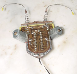
The whole circuit was assembled on a homemade PCB. The two motors were acquired from cell-phone vibrators; any other small efficient motors can be substituted. The motors were attached directly to the PCB using the feviquick glue. It is necessary to attach them at the correct angle of about 40 to 45 degrees to the horizontal for getting good traction. The power is provided to the robot using two long wires (4.5v to 6v)
Working:
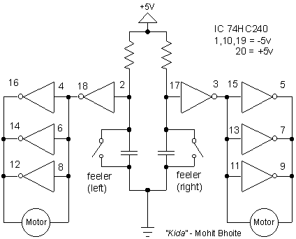
This circuit employs 8 inverter gaits; the two in the center are the main control gaits while the three on either side are used to drive the motor. Now let’s see how the circuit actually works:
Step1:When the robot is turned on, it reverses for a moment and then continues to move in forward direction. Initially, the two capacitors are charging, hence the inputs 2 & 17 of the two main gaits get pulled down to ground. This in turn makes the group of three inverters to provide positive and negative voltage to the two motors which makes the robot turn in backward direction. When the capacitors are fully charged, the capacitor stops conducting and the whole Vcc is directed towards the input of the two main gaits, this reverses the polarity of the motors and the robot moves forward motion.
Step2: When one of the feeler strikes an object, it short circuits the capacitor leading to its discharging. Therefore, the input of the respective gait is pulled to ground till the capacitor gets fully charged. Thus, the respective motor is reversed, which makes the robot turn in that direction. After the capacitor has fully charged, the input of the gait returns to the stable state and the robot continues to move in forward direction.
The value of the capacitors and the resistors depends on the angle of rotation you want your robot to make when it strikes an object. High values will result in higher degrees of rotation. In this robot, the caps were 0.22uf and the resistors were 3M (They might differ in your case).
The whole circuit should be tested on a breadboard and then soldered on to a PCB. This will make the debugging easier and the values can be well estimated beforehand.
Parts List:
IC 74HC240 – 1
Capacitors (ceramic) 0.22uf – 2
Resistors 2M – 2
Motors – 2
PCB Wires, etc.


