Basanti
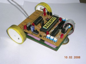
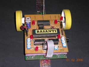
Basanti is my second line following robot. She was specially built for a local robotics competition. The task was to detect junctions and the presence of mirrors (placed on the sides) while taking appropriate turns on the way. Initially I decided to modify my previous line follower Dizzy but I soon realized that modifying her was as good as building a new robot altogether. And secondly I didn’t want to program it in assembly.
I recently used PIC 18F452 microcontroller in one of my projects. It is a very powerful chip and is supported by Microchip’s very own C18 C compiler. A 60days student’s trial version is available for free download. Hence, this chip turned out to be the obvious choice for Basanti.
I wanted to keep the design as small as possible. Small robots are easy to handle, easy to test and above all require small space to build. Since I have a small bedroom and an even smaller desk, the idea of keeping things small suits me perfectly. Basanti’s construction is very similar to Dizzy. The PCB itself acts as the body of the robot, lids of old medicine containers are used as wheels while thick rubber bands turn into tyres. A very compact design in the end!
The sensors:
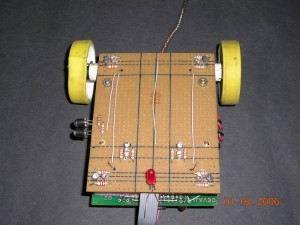
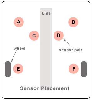
Basanti uses 6 infra-red emitter-detector pairs to track the line. But only two of these pairs are used to actually follow the line, the other four are used to detect junctions and for alignment during turns. An additional IR sensor pair is used to detect the presence of a mirror on her left side.
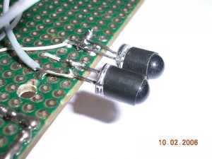
I had a few 3mm IR emitter/detector lying around in my drawers for a long time. They seemed to be an ideal choice for Basanti. Due to their small size I decided to mount these sensors directly under Basanti’s belly (on a separate bottom PCB.)
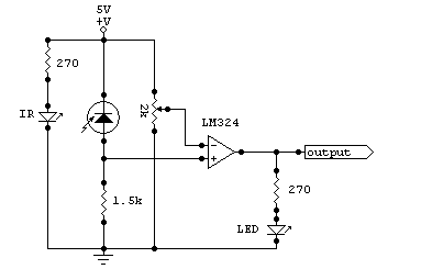
The line detector circuit is a simple comparator built using IC LM324. The threshold is set using the 2k pot. To ensure that the IR led doesn’t unnecessarily heat up too much, a current limiting 270 ohm resistor is connected in series with it. The indicator led at the output comes in handy when tuning the sensors. The threshold can be easily adjusted to detect a white paper line, white paint line or a sliver tape line on a black surface.
The procedure is simple, here’s how: (I would recommend you to test this circuit on a breadboard first)
- Make sure the power supply is ON, now see if the indicator led is lit or not. If lit then turn the pot in one extreme direction so that it turns off completely and if its not lit then first turn the pot so that it turns ON and then turn it in the extreme opposite direction so that it turns off. This test proves that the comparator is working properly.
- Now place a white paper or the sample material used for the line on top of the sensor pair at a distance of about 5mm to 10mm.
- Then slowly turn the pot in one direction until the indicator led just lits up.
That’s it, we now have a simple line detector ready to use!
(TIP: To check if the IR led is working properly, use a cell phone camera, web-cam or a digi-cam to look into it, since CMOS/CCD sensors inside these cameras are sensitive even to the infrared region, you’ll be able to see it lit!)
The idea of following the line is very straight forward. Sensors C & D are arranged such that they lie just outside the edge of the line. The algorithm is as given below:
/Sample code for a line following robot/

void main(void)

{

while(1)

{

if(sensor_C==1 && sensor_D==0)

left ();

if(sensor_C==0 && sensor_D==1)

right ();

if(sensor_C==0 && sensor_D==0)

forward();

}

}
void right(void) //generates suitable bit patterns for the motors to turn right

{

left_motor1=1;

left_motor2=0;

right_motor1=0; //stops the right motor

right_motor2=0;

return;

}
void left(void) //generates suitable bit patterns for the motors to turn left

{

left_motor1=0; //stops the left motor

left_motor2=0;

right_motor1=0;

right_motor2=1;

return;

}
void forward(void) //generates suitable bit patterns for the motors to move forward

{

left_motor1=1;

left_motor2=0;

right_motor1=0;

right_motor2=1;

return;

}
